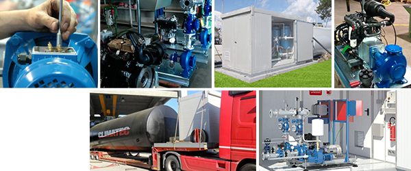
DESCRIPTION
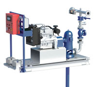
The fire prevention unit is made up of a Vertical Turbine type service pump driven by an endothermic diesel cycle motor and a submerged electric compensation pump that consists of two modules.
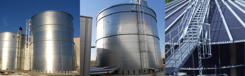
The first will be positioned above the water storage tank and consists of a base on which they are mounted:
- An endothermic diesel cycle engine connected by cardan joint to the main pump control unit
- The two delivery pillars for the pumps including all accessories required are in accordance with standard UNI-EN 12845.
- An interconnection collector
- An iron framework on which the electrical control panels for the two pumps, the fuel tank for the diesel engine and its collection tank are installed.
- Batteries to start the diesel engine
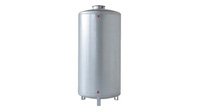
The second consists of the actual pumping parts which will be immersed in the water storage tank and hydraulically and mechanically connected to the delivery pillars located on the base of the first module. The service pump, equipped with a foot valve and an anti-vortex plate, will be connected by means of a shaft line that acts as a transmission shaft and delivery pipe at the same time.
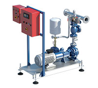
COMPONENT BASE
A thick base made of galvanised pressed steel, consisting of a double frame with vibration-damping supports. An electro-welded iron truss is connected to the base to support the electrical panels, tank and fuel collection tank.
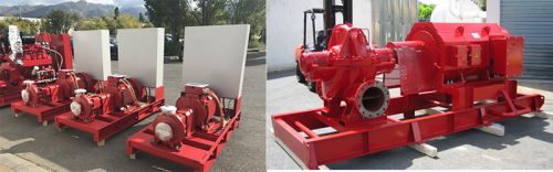
SERVICE PUMP
Submersible centrifugal service pump with a vertical axis of the axial flow type, multi-impeller, manufactured with cast-iron stage supports and impellers, complete with foot valve with anti-vortex plate and suction strainer. Connection to the endothermic diesel engine via the control unit and axle line.
The engine is designed to provide the maximum power absorbed by the pump according to ISO 3046 (par.10.9.1), direct injection, air-cooled or water-cooled with radiator or heat exchanger.
The motor-pump unit is equipped with an electric control panel, built to UNI-EN 12845 standards, with a set of two starting batteries (par.10.9.8), fuel tank and recovery tank for fuel leaks or spillage up to 100% of its capacity (par. 10.9.6).
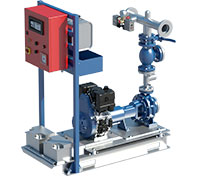
PRESSURE COLUMN SERVICE PUMP
It mainly consist of:
- Concentric reduction to keep the water speed within 6 m/sec, (as indicated by the standard).
- Recirculation device (2% of flow rate) (par. 10.5)
- Pump pressure switch in operation
- Inspectional check valve
- Pressure switch test circuit with two starting pressure switches (par. 10.7.5.1) and glycerine bath pressure gauge
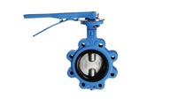
- Wafer exclusion valve
- Delivery manifold - Equipped with connection for the pilot pump, connection for flow meter and connection for technical room sprinkler kit (accessory)
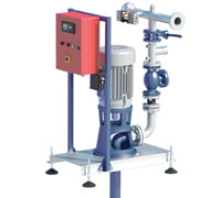
COMPENSATION PUMP
The compensation pump is submersible, which can be cooled by, pumped liquid or by a 4” multi-impeller which is cooled by its surrounding liquid. It is connected to the main pump manifold via a discharge pillar on which the following components are installed:
- 01 Non-return valve
- 01 shut-off valve
- 01 pressure switch
- 01 pressure gauge
- 01 20L autoclave vessel for maximum operating pressure of 16 bar.
- 01 Control panel in compliance with EN 12845 standards. In units with a service pump having a delivery head of less than 8 bar, the above-described components could be replaced by Pressoflussostat specifically designed for pumps installed on fire prevention units.
The compensation pump starts and stops automatically when the pressure is restored.
Motor pump control panel in compliance with UNI-EN 12845 standards with integrated SUPERVISION remote control and telemonitoring device.
The main electric pump panel is constructed with certified components assembled inside a metal box protected by RAL 3000 paint powders based on electrostatically applied synthetic resins, which are highly resistant to corrosion. The system is managed by a highly reliable and robust electronic control unit that fully meets the requirements of EN 12845. All electrical measurements and motor controls are shown on a backlit display.
The standard version is certified for IP 54 protection, IP 55 and IP 56 are manufactured on request.
Inside the switchboard is the brand new SUPERVISION, high-tech remote control and telemonitoring device, specially designed to remotely control and monitor all the functions of the fire prevention unit via the web in real-time, using a PC, Smartphone or Tablet. This allows the user to take advantage of the numerous services offered by the dedicated portal, from simple alarm signalling to, useful management of periodic maintenance; from useful consultation on the state of efficiency of the equipment to, keeping a record of all the important events that have occurred during the life of the pumping unit.
STANDARD CONFIGURATION
- IP 65 metal case painted with RAL 3000 resin-based powder coating.
- Door lock with removable key
- 1P+N general lock-door disconnector for auxiliary power supply input
- Motor pump inhibition key switch
- Motor stop button
- Pair of emergency start buttons from the battery
- Pre-programmed electronic control unit for diesel engine control and management
- 2 battery chargers each for 12Vdc 5A battery charging and control.
- Fuse holders and accessories for power and auxiliary circuits
- 2 power relays.
- Connection terminal board
- Supervision GPRS Gateway module for remote control and telemonitoring
ELECTRONIC CONTROL UNIT
Programmed to comply with current legislation and technical standards:
DESCRIPTION
-
Compact and functional design with easy-to-use keypad
-
High weather resistance IP65
-
Wide operating temperatures range from -10°C to +40°C
-
Backlit display consisting of 4 lines of 20 characters each.
-
Automatic fuel autonomy control.
-
Standard remote control
-
Service management
-
Scheduled maintenance required by UNI-EN 12845 regulations
-
Manual test function for motor-pump start-up in compliance with UNI-EN 12845 standards.
-
Self-powered by battery
-
An integrated flash memory of 47 events
MEASURING EQUIPMENT
- 2 Battery voltage voltmeters
- 2 Amperometers charging current
- Fuel level
- Coolant temperature
- Oil pressure
- Engine frequency in RPM
- Date and time
- Event history (47 total events)
- Cumulative hours of operation
- Battery charger management
- System or main pump alarms
- Engine heating management via temperature reader
- Fuel gauge (optional)
- Weekly or monthly self-test (optional)
- Coolant cycle
It is possible to switch the unit to UNI 10779 operation, with a programmable stop time from a digital display.
Inside the electrical panel, there is a terminal board that allows the transfer of the main (four) alarms provided for by the law that signal the presence of malfunctions of the pumping unit or its intervention due to the presence of fire, to a special apparatus equipped with visual (lamps or LEDs) and acoustic (siren) warnings, placed in a supervised environment. The connection between the two systems is made via electrical cables. Other systems using the GSM network, with an appropriate SIM card, can transfer the same signals to a fixed or mobile telephone device.
CLIMATEC, on the other hand, integrates the components of its switchboards with a device called Supervision, which makes it possible to check the status of the fire prevention unit from anywhere in the world, even when it is not in use.
Supervision
is a GPRS communication gateway device that integrates with a specific technological platform (portal) designed to extend the ability to control and supervise the system via the Internet using a Web browser on PC/MACs, Smartphones or Tablets. It allows constant monitoring, even in groups, of all the main parameters relating to the operating status of a fire prevention unit built in accordance with UNI-EN 12845, and of all the other accessory functions not provided for in the standard. Supervision retrieves, at regular and programmable intervals, all the information in the switchboard control units and transmits it to the portal cloud, making it immediately available for consultation by the user. Since the connection to the platform is two-way, it is possible for the user to get information directly from the unit, especially when malfunctions occur or problems arise that trigger the alarm signals. In this case, by means of prior setting up, it is possible for these signals to be sent by SMS and/or email also to intervention centres such as Assistance Centres, Fire Brigade, Police…
The system makes it possible to schedule the periodic maintenance operations required by the law and to activate remote tests; The portal acts as a data logger for the whole system, recording the main events that have occurred in the unit and providing a reliable report on the history of faults and the correct execution of weekly and periodic tests. These reports can be provided to the supervisory bodies to demonstrate the accuracy of the operations carried out or the exact moment when an event occurred (e.g. fire).
Main parameters of which Supervision allows remote monitoring for motor pumps with panels built to EN 12845 standards.
- Voltage status / Voltage failure
- Pump Start Test / Failure to Start
- ECU efficiency / ECU memory error
- Pump running
- Pressure switch call
- Battery A status/Battery A alarm
- Battery B status/Battery B alarm
- Battery A alarm disconnected
- Battery B alarm disconnected
- Battery charger A status/ Battery charger A failure
- Battery charger B status/ Battery charger B failure
- Oil temperature status/oil temperature alarm
- Oil heater status/oil temperature alarm
- Oil level status/oil level alarm
- Water temperature status/Water temperature alarm
- RPM sensor status/rev. sensor alarm
- Fuel level status/Fuel shortage alarm
- Mains pressure status
- Priming tank liquid status/Priming tank float alarm
- Starting prevented
- Communication with control unit interrupted / remote reset test
- Consultation and printout of the document archive on which wiring diagrams, photos of the system, component manuals, test reports, etc. can be stored.
TECHNICAL FEATURES:
GSM/GPRS connections
Protocols: open, Modbus RTU and TCP/IP
Multilevel username and password protection
Multi-user, multi-level, multi-language platform
Multiple connections from several remote devices allowed
The entire range of CLIMATEC units are CE-marked and comply with the regulations:
- machinery directive 98/37/EC
- Electromagnetic compatibility directive EMC 2004/108/EC
- Low-voltage directive LVD 2006/65/EC
- The construction criteria of all our units comply with UNI - EN ISO 9001:2008.